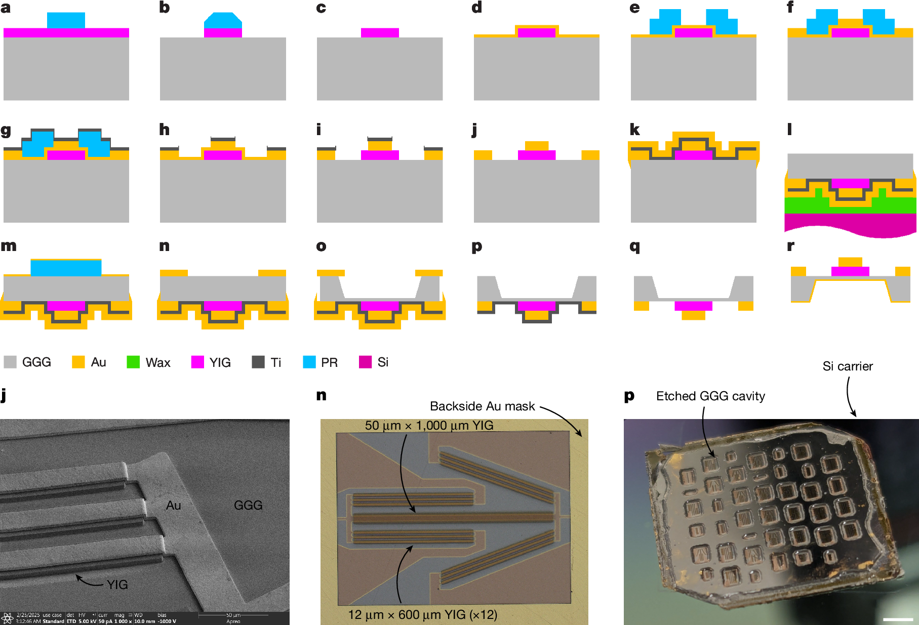

A microwave filter can be built from metal traces, resonators and electrical networks. It can also be built from a disturbance moving through the magnetic moments of a crystal. The second possibility has occupied researchers for decades, but a new generation of micromachined yttrium iron garnet devices is beginning to resolve the problem that held it back: turning an elegant spin-wave experiment into a compact, tunable component whose performance can actually be measured at the RF ports.
A radio receiver must separate one signal from thousands of unwanted neighbors. That task has become harder as wireless hardware moves into crowded, high-frequency bands and demands larger instantaneous bandwidth. Conventional acoustic filters have formidable manufacturing advantages at frequencies below roughly 6 GHz, yet their performance and footprint become increasingly difficult to reconcile with the tuning requirements of emerging FR3 radio architectures. Reconfigurable magnetic resonators offer another method. Instead of relying only on charges oscillating in metallic conductors or on acoustic strain, they couple an electrical signal into the collective precession of spins and recover a modified signal at another port. [1][2]
In February 2026, Connor Devitt and collaborators reported spin-wave ladder filters in Nature with magnetic tuning from 7.08 to 21.6 GHz, bandwidths as large as 663 MHz, and measured insertion losses between 2.54 and 5.78 dB in their third-order designs. The active filter occupied about 1.566 mm². Crucially, a single magnetic bias controlled resonators whose frequencies had been separated through lithographically defined geometry. The team also placed a tunable filter in a quadrature-amplitude-modulated radio receiver and measured interference rejection. That is a more demanding claim than merely detecting a spin wave on a laboratory instrument. [1]
To understand why this matters, it is worth returning to an earlier and less glamorous experiment. In 2015, a dual-waveguide YIG sensor used an opposed magnetic bias to cancel temperature-induced phase drift. The original experimental figure, reproduced below, makes the essential engineering point visible: magnetic waves are controllable, but the instruments, antennas, magnets and surrounding temperature are part of the device. A practical magnonic circuit must be designed around all of them. [3]
A wave that travels through magnetic order
In a ferromagnet or ferrimagnet, neighboring spins interact through exchange and dipolar fields. At equilibrium the net magnetization points along a preferred axis set by an external field, internal anisotropy and sample geometry. A microwave magnetic field applied transverse to that direction tilts the magnetization. Rather than simply returning to equilibrium, the local magnetic moments precess, and the disturbance can propagate through the material. These collective waves are called spin waves; their quantized excitations are magnons. Classical microwave circuits usually launch large coherent populations of magnons, so observing spin-wave transmission does not by itself establish a single-magnon quantum device. [2][4]
The starting point for the dynamics is the Landau–Lifshitz–Gilbert equation. In a common convention,
Here is the magnetization, its saturation value, the effective magnetic field, the magnitude of the gyromagnetic ratio and the dimensionless Gilbert damping constant. The first term describes precession, the second relaxation. Exchange, applied bias, demagnetizing fields and anisotropy all contribute to . The linearized equation produces an excitation spectrum whose slope determines the spin-wave group velocity,
Wavevector, group velocity, damping and film thickness determine how far an RF signal can propagate before its spin-wave component becomes too small to be detected. The actual dispersion is mode and geometry dependent. Damon–Eshbach surface waves and forward-volume modes, for example, possess different directional behavior and boundary conditions; a single universal dispersion formula would hide that distinction. [2][4]
Why YIG is unusually useful
Yttrium iron garnet, , is an electrically insulating ferrimagnet with exceptionally low magnetic damping when grown with high crystalline quality. Spin-wave energy can propagate through its ordered magnetic moments without a net electronic charge current flowing along the waveguide. That reduces an important class of resistive propagation losses, although it does not remove the losses of the antennas, transmission lines, magnetic excitation or external electronics. This difference is fundamental: low intrinsic material damping is not the same thing as low end-to-end insertion loss. [2][5]
Single-crystal YIG films are frequently grown on gadolinium gallium garnet, or GGG, because the garnet substrate offers a good crystallographic match. High-quality epitaxy is valuable, but neither material name guarantees the same performance across thickness, wafer position or processing method. Film linewidth, surface roughness, magnetic inhomogeneity, patterned edges, stress and temperature all affect the measured response. A film that appears excellent under broadband ferromagnetic resonance can still perform poorly when integrated with a micron-scale antenna or a complicated multilayer assembly. [5][6]
This is where an apparently minor measurement issue becomes important. A YIG device may display a beautifully narrow magnetic resonance while most of the electrical input power reflects from an impedance mismatch. Equally, a direct electromagnetic path between two adjacent RF probes can create an apparent transmission peak even when the magnetic channel contributes almost nothing. Magnetism does not remove circuit engineering. It adds another channel that must be separated from the circuit's parasitic response.
The 2015 experiment: removing temperature without removing the signal
A permanent magnet offers a convenient bias field for a microwave spin-wave circuit. Unfortunately, the magnet's field changes with temperature. YIG saturation magnetization is temperature dependent too. Both effects shift the allowed magnetostatic-wave frequency band, producing a phase drift at fixed microwave frequency. A sensor interpreting every phase change as an external magnetic field would confuse the environmental temperature with the quantity being measured. In 2015, Taichi Goto and collaborators built a spin-wave differential circuit to separate those effects. [3]
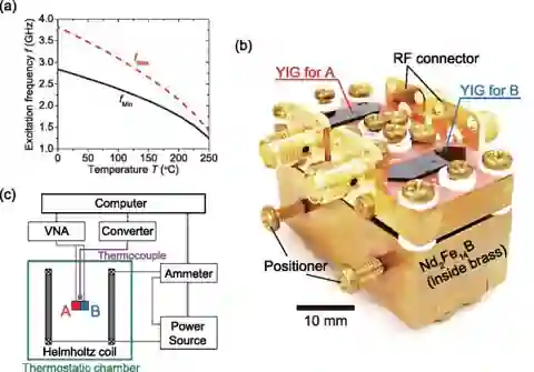
Two YIG films were mounted over patterned microstrip lines and magnetized in opposite directions by adjustable neodymium–iron–boron magnets housed in a brass fixture. The setup included RF connectors, positioning screws, a Helmholtz coil, a thermocouple, a thermostatic chamber and a vector network analyzer. The left panel shows why the magnetostatic-wave frequency window shifts with temperature. The center and lower panels show how the two physical channels were assembled and measured. This is a temperature-compensated sensor, not a photograph of the newer wafer-scale band-pass filters.
Let the measured transmission phases be and . Their difference is
If the two channels have similar temperature coefficients but opposite magnetic-field responses, a first-order expansion near an operating point gives
The first coefficient can be made small by matching the two channels, while the second need not cancel because the opposite magnetization directions create distinguishable magnetic responses. The team reported a differential temperature coefficient around per kelvin, compared with approximately per kelvin for a single channel, a suppression factor of about 2,100 in the tested conditions. The residual drift was attributed to differences in channel geometry and propagation characteristics. The achievement was not eliminating temperature dependence from YIG. It was designing a measurement in which most of its effect became common mode and could be subtracted. [3]
The lesson extends well beyond field sensing. If a reconfigurable RF filter is to hold a specified center frequency, its controller must know whether a frequency shift came from an intended magnetic bias change, material heating or long-term drift. A calibrated module requires reference measurements, temperature monitoring and an explicit plan for recalibration. Two nominally identical waveguides are not necessarily equivalent after assembly, wire bonding, mounting and repeated thermal cycling.
Why a low-damping material can make a poor RF component
To enter a magnonic device, microwave power must first excite a time-varying magnetic field near the YIG. A microstrip, loop or ground–signal–ground (GSG) coplanar structure can produce that field. At the far end, a second conductor converts the propagating magnetic disturbance back into an electrical voltage. The total transmission therefore includes electrical injection, magnon propagation and electrical pickup. Each stage can lose power. A 2025 experimental and modeling study by Erdélyi and collaborators analyzed this problem using circuit-level models coupled to micromagnetic simulations. [5]
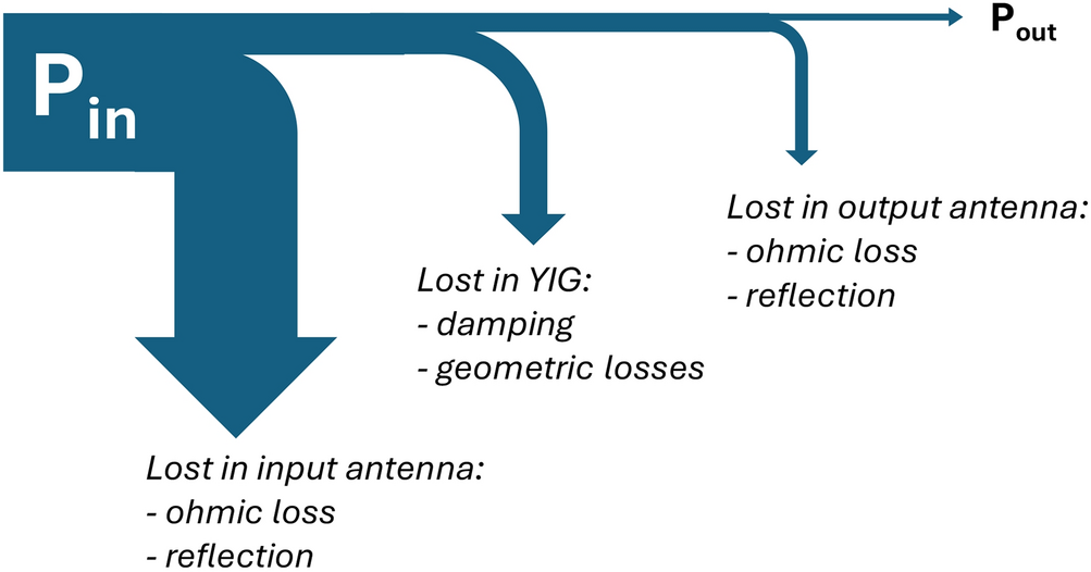
For two calibrated microwave ports, a common insertion-loss convention is
where is the forward complex scattering parameter. For example, a measured loss of 5 dB corresponds to a transmitted power fraction , or about 32%, relative to the selected calibration reference planes. A 5 dB design claim is not equivalent to a direct measurement of 5 dB on a physically constructed device. Erdélyi and colleagues designed a transducer pair predicted to achieve roughly 5 dB insertion loss over a 100 MHz band and validated major parts of their modeling against separate experiments. A May 2026 *Physical Review Applied* study later reported measurements that reduced insertion loss below 10 dB in microscale YIG spin-wave transducers. These results should be described according to what was actually modeled or measured. [5][7]
Ground–signal–ground probes and shorted microwave antennas are therefore not incidental fabrication details. Their contact geometry, resistance, port impedance and field overlap with the desired wave mode determine whether energy reaches the magnetic system. Impedance matching reduces reflection, but excessively broad RF coupling can excite unwanted spin-wave modes. Reducing antenna dimensions helps miniaturization while sometimes increasing ohmic resistance and magnetic mode mismatch. Optimizing one quantity in isolation commonly makes another worse.
Direct electromagnetic feedthrough can impersonate a magnon
Place two RF antennas close together on a small die and an additional electromagnetic path may couple them without propagating through the YIG at all. At the measured output, the voltages from direct feedthrough and the spin-wave pathway add coherently. In a simple linear model one may write
The spin-wave term can have a rapidly varying phase because the wave accumulates a propagation phase , in addition to attenuation. Direct feedthrough may instead vary smoothly with frequency and be relatively insensitive to magnetic bias. Their interference can create both peaks and nulls in the total transmission. Consequently, a visually dramatic notch is not sufficient evidence that an intended spin-wave filter is functioning.
A credible measurement workflow identifies the VNA calibration planes and records both magnitude and phase of and . Bias-field sweeps distinguish magnetic excitations from many electrically coupled backgrounds. Measurements on reference structures with no YIG, appropriately terminated antennas and multiple antenna spacings help isolate direct transmission. Time-domain processing of broadband S-parameters can sometimes distinguish a delayed spin-wave signal from prompt electromagnetic feedthrough, although bandwidth and dispersive propagation limit that separation. The reported magnetic transmission should survive these controls rather than appearing only after an arbitrary background subtraction. [5][7]
A single magnetic field, two resonant frequencies
The February 2026 Nature paper addresses a major architectural complication in spin-wave filters. Conventional ladder filters contain series and shunt resonators with carefully offset resonant and antiresonant frequencies. Producing those offsets with separate magnets increases size and complicates a multi-stage design. Devitt and collaborators instead changed the geometry of patterned YIG regions so that the internal magnetic field and spin-wave wavevector varied between resonators exposed to the same applied bias. [1]
For an out-of-plane magnetized film, the effective field can be approximated by
where depends on the resonator's shape and magnetization direction. The frequency of the selected spin-wave mode depends on this effective field and its allowed wavevector. By using wider YIG mesas for one resonator type and parallel narrow YIG fins for another, the team engineered the separation needed for a ladder filter without adding a second independently controlled magnetic field. That is a geometrical solution to what once seemed a magnetic-biasing problem. [1]

The device used carefully patterned 3 µm YIG films and deep anisotropic etching of the GGG substrate. Such processing changes the achievable resonator geometry, inductive coupling and parasitic losses. The reported high chip-level yield supports the possibility of wafer-scale manufacture, but is not equivalent to demonstrating that millions of packaged filters meet commercial yield, lifetime and environmental specifications. The external magnetic bias and its packaging still need to be miniaturized and qualified. A microfabricated resonator is only one component of a manufacturable RF module. [1]
The measurements that make the 2026 filter important
The central experimental figures are not a speculative speed or energy advantage. They are measured RF quantities. The third-order devices demonstrated center-frequency tuning from 7.08 to 21.6 GHz, an insertion loss between 2.54 and 5.78 dB, and bandwidths up to 663 MHz, with a filter footprint of approximately 1.566 mm². Their out-of-band rejection, reported at a defined offset from the passband, ranged from 3.64 to 13.84 dB. Higher-order filters improved rejection at the cost of additional components and other trade-offs. The study also reported input-referred third-order intercept points above 11 dBm for selected operating conditions. [1]

Bandwidth and tuning range should not be conflated. A device that can move its center frequency by many gigahertz does not pass that entire interval simultaneously. Its instantaneous bandwidth is the span admitted at one magnetic bias setting. Likewise, a low insertion loss at the best bias field does not imply that the same loss, rejection and linearity hold across the full tuning range. Practical RF specifications are tables of simultaneous operating constraints, not independent records selected from unrelated conditions.
A third-order intercept point, or IIP3, is obtained by extrapolating the linear input-output behavior of the desired signals and their third-order intermodulation products. It gauges susceptibility to distortion from two strong nearby tones; it is not a direct statement of the maximum safe input power or the filter's quantum coherence. For a dense communications spectrum, nonlinear spurs can be as troublesome as linear leakage. That is why the study measured linearity in addition to frequency selectivity and checked device performance in a working receiver. [1]
From a resonator to a working receiver
A filter that displays an appealing VNA trace may still fail in a transceiver. An actual receiver must demodulate information while suppressing interference, maintaining sufficient signal-to-noise-and-interference ratio and tolerating neighboring signals at different powers. Devitt and collaborators included their tunable spin-wave filter in a radio test and measured quadrature-amplitude-modulated outputs under nearby interference. The experiment connects the magnetic resonator's S-parameters with the ability to receive an encoded signal. It is a meaningful system-level demonstration, but it is not yet proof of broad commercial deployment or replacement of every acoustic filter. [1]

For a filter to be practical, the control electronics must settle accurately after a frequency change, the magnetic bias must be stable against temperature and mechanical variation, and the attenuation outside the band must be strong enough for the complete receiver chain. Packaging can also alter a carefully tuned circuit through magnetic field gradients, RF ground return geometry or coupling to nearby metal. The older differential YIG sensor and the newer wafer-compatible filter attack different parts of the same engineering problem: convert a magnetic response into an RF quantity that remains useful when the laboratory surroundings stop being ideal.
Programmable magnetic circuits need not have fixed wave paths
A separate experimental direction explores changing the spin-wave medium itself after fabrication. In 2025, Zenbaa and collaborators reported a YIG-based inverse-design platform in Nature Electronics equipped with 49 individually driven current loops. Those loops generated a programmable spatial magnetic field above the film. A feedback algorithm adjusted the currents to realize functions including an RF notch filter and a frequency demultiplexer, directly using measurements to guide the search rather than relying entirely on simulated forward models. [8]
The appeal is functional reconfiguration: one piece of magnetic hardware can be tuned toward different frequency-response objectives. The limitation is equally physical. Forty-nine current sources require control hardware, wiring, thermal management and repeatable calibration. A favorable loss or footprint for the magnetic propagation region does not automatically imply a more efficient system when the bias circuitry is counted. This is a recurring lesson of engineering at small scales: the surrounding apparatus must become part of the reported performance.
What distinguishes a useful prototype from a materials demonstration?
The next generation of magnonic modules will be judged across several coupled gates. One is the quality of the magnetic film, characterized through saturation magnetization, damping, resonance linewidth, roughness and thickness uniformity. Another is the antenna interface, where port matching, RF ground return, coupling bandwidth and direct feedthrough are quantified. A third is magnetic bias and thermal stability, including hysteresis and tuning repeatability. Finally, devices must be fabricated, packaged and retested with calibration references that make their performance comparable to acoustic filters, ferrite components and conventional tuned RF circuits. [1][5][6]
For a propagating spin wave with attenuation length and waveguide length , a simplified amplitude envelope behaves as if is defined as the amplitude decay length. The associated magnetic propagation contribution to power loss then scales as . This formula alone does not calculate port-to-port insertion loss because antenna coupling, multiple reflections, modal conversion and direct electromagnetic paths may dominate the measured response. It does reveal a design trade-off: longer paths can provide more phase shift or filtering structure while increasing magnetic attenuation, and miniaturization changes the wavevector selection and coupling efficiency.
The final hurdle is honest comparison against the alternatives. Commercial acoustic filters benefit from extraordinary manufacturing maturity, cost optimization and repeatable packaging. Existing YIG oscillators and ferrite filters have a long history of tunability. The new question is whether micromachined, calibrated thin-film devices can combine multi-octave adjustment, hundreds of megahertz of instantaneous bandwidth and competitive noise and loss without an impractically large magnetic assembly. The 2026 results show an encouraging combination of those properties, not a completed answer for every radio standard.
Where quantum magnonics actually enters
Magnons are quantum quasiparticles, but most microwave spin-wave filters operate in a classical, many-magnon regime at ambient or controlled laboratory temperatures. Quantum magnonics requires stronger claims: preparation or detection of nonclassical magnon states, coherent coupling to a qubit or resonator, and measurement of quantum correlations or state-transfer fidelity. Thin-film YIG spin-wave propagation has been measured down to tens of millikelvin, which supports the feasibility of combining magnonic waveguides with cryogenic architectures. Yet low-temperature propagation does not, by itself, constitute a fault-tolerant quantum gate or a quantum memory. [9]
A sensible near-term direction is therefore to value magnonics for what it already accomplishes. Its magnetic tunability and compact wavelengths can create unusual RF filters, interferometers and sensors. Its high-quality low-damping materials can support experiments in coupled oscillator physics. If the same fabrication and measurement discipline eventually yields low-noise single-magnon components, the quantum applications will have a credible foundation. There is no need to disguise a strong microwave-engineering result as a completed quantum processor.
The most significant change in recent magnonics is not that electrons have been eliminated from the device. Metal traces, bias circuits and VNA ports are still indispensable. What has changed is where the useful frequency-selective dynamics occur. A patterned crystal of ordered spins can now carry part of the function that once required large fixed-frequency RF structures, and the magnetic structure can be tuned after fabrication. Whether such circuits become routine hardware will depend less on dramatic wave pictures than on measured losses, controlled parasitics, reliable calibration and repeatable manufacturing.
References
[1] Devitt, C., Tiwari, S., Zivasatienraj, B. and Bhave, S. A., Spin-wave band-pass filters for 6G communication, Nature 650, 599–605 (2026). Original experimental paper.
[2] Levchenko, K. O., Davídková, K., Mikkelsen, J. H. and Chumak, A. V., Review on Spin-Wave RF Applications, IEEE Transactions on Magnetics 62, 0900140 (2026). RF engineering review.
[3] Goto, T. et al., Spin wave differential circuit for realization of thermally stable magnonic sensors, Applied Physics Letters 106, 132412 (2015). Differential thermal compensation study.
[4] Stancil, D. D. and Prabhakar, A., Spin Waves: Theory and Applications, Springer (2009). Theory and device foundations.
[5] Erdélyi, R. et al., Design rules for low-insertion-loss magnonic transducers, Scientific Reports 15, 9806 (2025). Loss and transducer design.
[6] Askarzadeh, N. and Shokrollahi, H., Microwave device engineering with YIG materials, Journal of Applied Physics 138, 220701 (2025). YIG materials review.
[7] Kohl, F. et al., Identification and minimization of losses in microscale spin-wave transducers, Physical Review Applied 25, 054064 (2026). Measured transducer improvements.
[8] Zenbaa, N. et al., A universal inverse-design magnonic device, Nature Electronics 8, 106–115 (2025). Programmable field-driven devices.
[9] Knauer, S. et al., Propagating spin-wave spectroscopy in nanometer-thick YIG films at millikelvin temperatures, Physical Review Applied (2023). Cryogenic spin-wave propagation.
[10] Goto, T. et al., Three port logic gate using forward volume spin wave interference in a thin yttrium iron garnet film, Scientific Reports 9, 16472 (2019). Integrated spin-wave interference.
[11] A wideband tunable, nonreciprocal bandpass filter using magnetostatic surface waves with zero static power consumption, Nature Communications (2026). Alternate magnetically biased filter architecture.