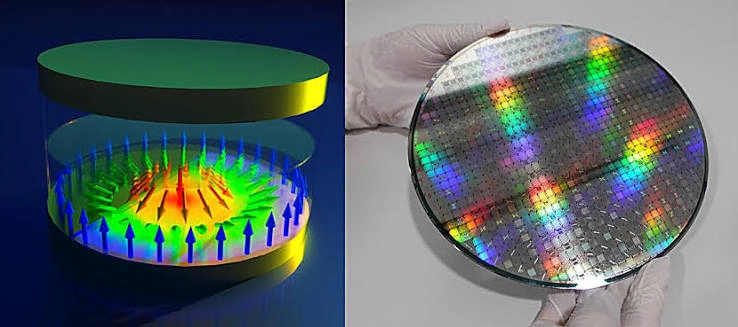

Imagine a memory chip in which the information moves and the reader stays still. Instead of addressing a grid of magnetic cells, an electrical pulse pushes a line of swirling spin textures along a narrow racetrack. Every texture can represent a bit, and each bit reaches a fixed detector in sequence. A skyrmion racetrack sounds almost like a conveyor belt for quantum magnetism. Yet its real challenge is not making a vortex move. It is ensuring that it moves exactly one position, without vanishing, splitting, sticking, or taking a neighboring bit with it.
This problem puts topological magnetism directly into contact with the demands of chip engineering. Experiments have demonstrated magnetic skyrmions only 80 nm in diameter moving through a 100 nm-wide track, electrical detection of mobile textures using tunnel magnetoresistance at room temperature, and a prototype skyrmion shift register with designed pinning sites. These are significant milestones, but they were not simultaneously demonstrated in one commercial memory array. The full memory cycle requires writing, transport, sensing, erasure and retention to work together. [3][4][5]
This is distinct from optical skyrmions, where polarization textures can be used to structure or measure light. A magnetic racetrack stores information in a fabricated ferromagnetic multilayer and moves the actual magnetization pattern under current pulses. It is also distinct from a generic skyrmion memory cell: the shift-register architecture gains density by sharing expensive reader circuits across multiple bit positions, but pays a price in latency and transport reliability.
A topological object becomes a logical bit
The original racetrack proposal used domains separated by magnetic domain walls. A skyrmion implementation can instead encode a one by a localized magnetic texture at a designated position and a zero by its absence, assuming that each bit cell has a sufficiently robust definition. No atom needs to travel down the device: the magnetization field changes in place, and the pattern propagates. The physical challenge is to ensure that the texture retains its size and structure during that propagation. [1][2]
For an ultrathin magnetic film, the unit magnetization vector m(x,y) defines a map from the physical plane onto a sphere of spin directions. Its winding can be quantified by a topological charge Q. In an ideal continuum with fixed boundary conditions, smooth transformations preserve this integer. Topological charge is not, however, a guarantee of indefinite retention in a finite device. A texture can escape through an edge or collapse when the magnetization develops the necessary nonuniformities.
From a memory perspective, the important question is the failure barrier against collapse, edge annihilation, accidental nucleation and thermally driven displacement. A skyrmion whose winding number is well defined in a microscope image may still be a poor bit if an ordinary read or shift pulse can destroy it. The distinction between topological stability and specified bit-error probability under real operating conditions will recur throughout this article.
Why materials engineering is already part of the logic
Skyrmions can be stabilized through competition between exchange stiffness, magnetic anisotropy, chiral Dzyaloshinskii–Moriya interactions, Zeeman effects and magnetostatic fields. In heavy-metal/ferromagnet multilayers, interfacial DMI favors chiral Néel spin structures. Adjacent layers can convert charge currents into transverse spin currents through the spin Hall effect, producing spin-orbit torques that translate the magnetic texture.
This schematic energy omits nonlocal magnetostatics, interlayer coupling and local fluctuations. Those omissions matter to fabrication. Grain boundaries and variations in film thickness can alter pinning; surface roughness can change the barrier for motion; a tunnel-junction deposition step can alter magnetic anisotropy. Consequently, the best skyrmion material for optical imaging is not necessarily the best stack for a dense, electrically readable memory.

Current pulses and the sideways skyrmion Hall effect
A magnetic skyrmion moves when spin transfer or spin-orbit torques reorient the local magnetization. The Landau–Lifshitz–Gilbert equation describes the full dynamics, including shape distortions, torque and damping. A rigid texture can often be approximated more economically as a particle-like object whose center follows a force balance. [2][13]
In the collective-coordinate relation, G is the gyrotropic coefficient, the dissipative factor D measures damping-related response, and U captures edges and pinning. The transverse force can redirect motion away from the racetrack axis. This skyrmion Hall effect threatens memory integrity because a drifting bit can reach an edge and annihilate. Different torque geometries and transient dynamics change the exact response, so an ideal expression for the Hall angle is a starting point rather than a complete prediction. [7]
Solutions include narrow-track confinement, patterned guiding potentials, compensated ferrimagnetic layers and antiferromagnetic skyrmions. Each solution changes other device parameters such as material complexity, drive efficiency or pinning thresholds. The engineering objective is a distribution of longitudinal displacements with negligible transverse annihilation, not merely the lowest value of a skyrmion Hall angle in a selected image.
Eight nanoseconds would already be useful; two were demonstrated
In 2024, Song and colleagues fabricated a FeGe nanostripe with a width close to 100 nm and followed magnetic skyrmions about 80 nm across using in situ Lorentz transmission electron microscopy. They applied current pulses as short as 2 ns and observed controlled longitudinal displacement. Geometrical confinement and edge-induced forces suppressed the net Hall motion, producing trajectories that were more nearly one-dimensional than a wide-track picture would suggest. [3]

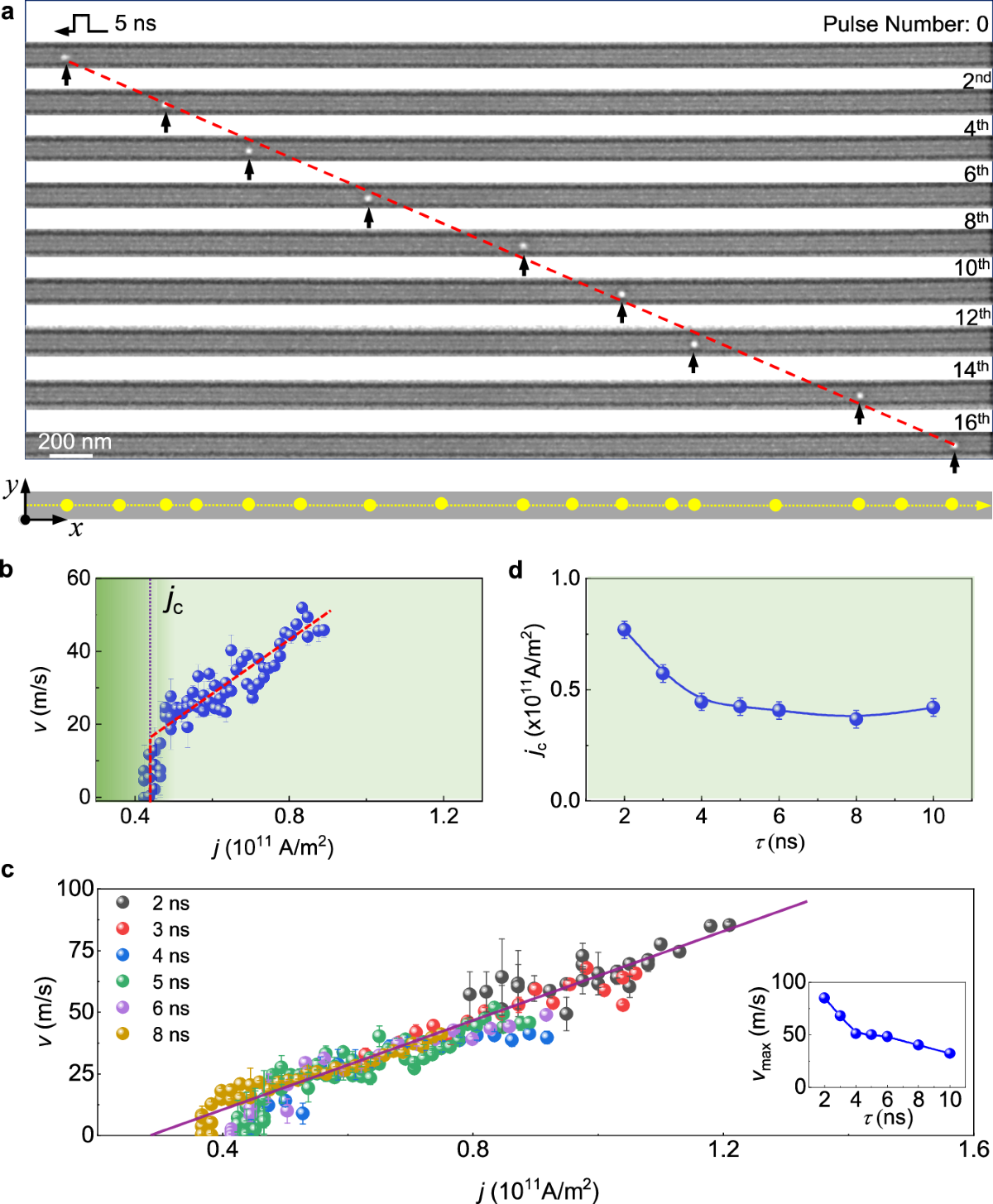
That is a narrow-track physics milestone, not proof of room-temperature CMOS-compatible mass storage. FeGe and the laboratory measurement conditions differ from the multilayers used in room-temperature tunnel-junction experiments. The significance is the measured response to confinement, including the finding that skyrmion position can continue to relax after a current pulse because of edge potentials and effective inertia.
Transport is not digital until a pulse lands in the right cell
A clocked shift register needs a defined bit pitch p. After one pulse, every bit should arrive inside a permitted window around the next cell. Average velocity by itself is insufficient. Two devices can have identical mean speeds but very different probabilities of missed shifts, double shifts, sideways loss and cumulative misalignment. The distribution of displacement after many cycles should therefore be a primary engineering measurement.
Here δ is the reader or trapping-site tolerance, which may be much smaller than the nominal cell pitch. Position noise is not necessarily independent or Gaussian. A persistent grain defect can cause the same bit to stall repeatedly. For intuition only, if independent shift errors occurred with probability pₑ, the chance of at least one error in N operations would follow the familiar repeated-trial formula.
Even a small per-pulse rate can become consequential after many cycles. For example, a hypothetical error probability of 10⁻⁵ per shift yields about a 9.5% chance of one or more errors in ten thousand independent shifts. This is a mathematical illustration, not a claimed experimental failure rate. True qualification must also measure correlated pinning, thermal loss and bit-pattern dependence.

One skyrmion is not an array
The displacement of a single texture cannot establish the behavior of a string of arbitrary data. Neighboring skyrmions can repel, attract or form bound pairs depending on the material and field configuration. Close spacing changes their mobility and can disrupt the designed bit pitch. The 2024 FeGe study examined isolated skyrmions, skyrmion pairs and chains, including several textures driven together. It thereby advanced beyond the simplest one-object experiment while still falling short of a statistical integrated register test. [3]

The right next step is testing random bit patterns across many cycles and devices. If a long sequence works only when every cell is occupied or every texture is far apart, it does not represent a general memory. Statistics should distinguish a true shift failure from a reader that temporarily missed an otherwise intact skyrmion.
Writing and erasing are physical operations, not assumptions
A writer must nucleate one skyrmion at a selected position without creating extra defects or disturbing its neighbors. Local notches or constrictions can concentrate spin-orbit torque and generate a reproducible texture; Büttner and colleagues demonstrated field-free deterministic nucleation with sub-nanosecond pulses in 2017. Pham and collaborators later showed voltage-controlled nucleation, erasure and electrical detection of a single skyrmion in a magnetic tunnel junction, combining these operations with magnetic imaging. [6][8]
The write error budget includes missed nucleation, extra nucleation, malformed textures, unplanned edge annihilation and heat or torque damage to nearby bits. An erase site presents similar hazards: it must remove the targeted texture without disrupting bits further along the track. The complete write-shift-read-erase cycle still requires integration and repeated verification on a common, manufacturable material stack.
A real reader uses tunneling magnetoresistance
Electrical readout can be performed by a magnetic tunnel junction above the track. A thin insulating barrier, commonly MgO, separates a reference magnetic electrode from a free layer. Spin-dependent tunnelling changes its resistance with relative magnetization alignment. A skyrmion beneath the junction changes the local magnetization pattern and therefore the measured tunnel resistance. [4][6]
This conventional TMR ratio compares uniform antiparallel and parallel electrode states; the contrast caused by a single skyrmion can be smaller and depends on its size, the junction aperture and partial overlap. Zhao and collaborators demonstrated TMR exceeding 100% at room temperature in Pt/Co/Ta-based skyrmion-compatible layers integrated with CoFeB/MgO tunnel junctions. They detected mobile skyrmions electrically in prototype racetrack-like structures, reporting resistance changes exceeding about 1.3 kΩ. These measurements are important because an electron microscope is not a practical memory reader. [4]

A production reader must separate zero and one levels over temperature, process variability and noise. Read energy, bandwidth and magnetic disturbance must be characterized simultaneously. A good TMR ratio is necessary but not sufficient: the full electrical distribution of bit values, the read margin and the probability of accidentally moving or destroying a bit during sensing are the quantities that matter.
A skyrmion shift register has finally been assembled
Another 2024 experiment came closer to register-like behavior. Zhao, Hua and collaborators used patterned surface indentations on Si/SiO₂ substrates and Ta/CoFeB/MgO multilayers to define a reproducible energy landscape. At room temperature, skyrmions shifted between adjacent indentations, while word-line and bit-line functions could be controlled separately. The prototype generated and moved skyrmion data sequences, rather than simply translating one magnetic spot. [5][15]
Intentional traps are both an advantage and a cost. They set stable bit positions but demand extra torque to escape. A deep trap can improve retention while increasing current consumption or creating a missed shift. A shallow trap can permit thermal wandering. The tradeoff must be optimized over actual operating temperatures and fabrication tolerances.
The hidden enemy is a granular energy landscape
Real thin films contain grains, edge roughness, thickness variation and spatially varying magnetic anisotropy. A skyrmion moving through this landscape does not experience a constant force or a perfectly smooth track. It can creep, become pinned or undergo a sudden depinning event. Castell-Queralt and collaborators modeled skyrmion survival at room temperature in granular racetracks, including thermal fluctuations and a stochastic transport equation. These were simulation results, not direct manufacturing yields, but they show why a reliability curve is more meaningful than a single speed measurement. [9]
For a thermally activated failure across an effective energy barrier ΔE, an Arrhenius lifetime approximation may be useful. Yet separate failure processes have separate barriers: internal collapse, lateral edge escape, depinning from a cell or accidental nucleation during a neighboring write. A single fitted lifetime is not a guarantee against all of them. Synthetic ferrimagnetic materials are another strategy for improving current-driven motion; experiments in 2024 measured their flow and depinning regimes under nanosecond current pulses. [10]

The trade between density, access time and energy
If L is the usable track length and p the spacing between bit positions, the idealized maximum number of nominal bits is roughly L/p. Reader and writer apertures, guard distances and electrical routing reduce the practical density. A physically small skyrmion is not sufficient if it cannot be moved and read reliably at a similarly small bit pitch.
The Joule expression counts only energy dissipated in a selected resistive path during a pulse. Peripheral drivers, tunnel sensing, interconnects and retries may dominate the system-level budget. A memory with few readers can improve storage density yet increase random-access latency because data must be shifted into position. Comparison with STT-MRAM, SOT-MRAM and domain-wall racetracks therefore requires matched retention, error rate, endurance, array layout and accessed-bit energy.
What would make the research device a credible memory
A convincing prototype would place a repeatable injector, controlled transport section, low-disturbance electrical reader and reliable eraser on one compatible magnetic stack. It should validate random patterns, not only an all-one chain, at room temperature across large numbers of cycles. Reporting only the fastest observed velocity or cleanest track would hide the tail of failures that determines useful storage.
The test matrix should vary pulse width and current, track width, bit pitch, temperature, operating field if any, read bias and repeated fabricated lots. Error classes should include missed writes, multiple writes, failed shifts, double shifts, accidental annihilation, read confusion and long-term retention loss. The measurements need confidence intervals and correlations, because one defective location can cause repeated failures.
The technology has passed a substantial physics threshold. It has not yet passed the complete engineering threshold. Its promise comes from the same controllable topology that makes the experiments so striking, but the next decisive result will be mundane in the best possible sense: a complete integrated array whose bits always arrive when summoned. That is the distance between observing a skyrmion and building a memory from it.
References
[1] Parkin, Hayashi and Thomas (2008), Magnetic Domain-Wall Racetrack Memory. https://doi.org/10.1126/science.1145799.
[2] Fert, Cros and Sampaio (2013), Skyrmions on the track. https://doi.org/10.1038/nnano.2013.29.
[3] Song et al. (2024), Steady motion of 80-nm-size skyrmions in a 100-nm-wide track. https://doi.org/10.1038/s41467-024-49976-6.
[4] Zhao et al. (2024), Electrical detection of mobile skyrmions with 100% tunneling magnetoresistance in a racetrack-like device. https://doi.org/10.1038/s41535-024-00655-1.
[5] Zhao, Hua et al. (2024), Realization of skyrmion shift register. https://doi.org/10.1016/j.scib.2024.05.035.
[6] Pham et al. (2024), Electrical Detection and Nucleation of a Magnetic Skyrmion in a Magnetic Tunnel Junction Observed via Operando Magnetic Microscopy. https://doi.org/10.1021/acs.nanolett.4c00316.
[7] Jiang et al. (2017), Direct observation of the skyrmion Hall effect. https://doi.org/10.1038/nphys3883.
[8] Büttner et al. (2017), Field-free deterministic ultrafast creation of magnetic skyrmions by spin–orbit torques. https://doi.org/10.1038/nnano.2017.178.
[9] Castell-Queralt et al. (2023), Survival of skyrmions along granular racetracks at room temperature. https://doi.org/10.1039/D3NA00464C.
[10] Durrant et al. (2024), Driving skyrmions in flow regime in synthetic ferrimagnets. https://doi.org/10.1038/s41467-024-52210-y.
[11] Woo et al. (2016), Observation of room-temperature magnetic skyrmions and their current-driven dynamics in ultrathin metallic ferromagnets. https://doi.org/10.1038/nmat4593.
[12] Song et al. (2020), Motion tracking of 80-nm-size skyrmions upon directional current injections. https://doi.org/10.1126/sciadv.aaz9744.
[13] Thiele (1973), Steady-State Motion of Magnetic Domains. https://doi.org/10.1103/PhysRevLett.30.230.
[14] Juge et al. (2021), Helium Ions Put Magnetic Skyrmions on the Track. https://doi.org/10.1021/acs.nanolett.1c00136.
[15] Zhao et al. (2024), Skyrmion shift register device overview. https://pubmed.ncbi.nlm.nih.gov/38960814/.