

A dilution refrigerator can cool its mixing chamber to ten millikelvin while microwave photons, cable center conductors, and even parts of the qubit's immediate environment remain much warmer. A 2026 experiment on nominally 0 dB attenuators exposes why the last few millikelvin are an engineering problem of their own.
At the bottom of a dilution refrigerator, a quantum processor sits within a remarkable thermal gradient. A room-temperature microwave generator sends pulses into a cable network descending through successive stages near 50 K, 4 K, hundreds of millikelvin, and finally the mixing chamber, where the thermometer may settle near 10 mK. The qubit chip is mounted to the coldest structure, often inside a carefully shielded enclosure. That arrangement makes it tempting to assign the entire device an operating temperature equal to the refrigerator's base temperature. But a thermometer attached to a copper plate reports the temperature of that plate. It says much less about the electromagnetic fields entering through a coaxial cable, the electrons in a resistive microwave component, or the center conductor passing through an insulating dielectric.
For a superconducting quantum processor, those distinctions affect the experiment directly. A microwave drive line is both an instrument for rotating a qubit and a physical channel through which the outside world can deliver thermal noise. Attenuators, filters, heat sinks, circulators, and cable materials determine how much of that world reaches the chip. Their design becomes particularly unforgiving below 100 mK, where a seemingly modest temperature difference can represent an enormous change in the population of microwave photons. The relevant question is not simply whether the refrigerator is cold enough, but which degrees of freedom have actually equilibrated with the coldest stage. [1][2][3]

The refrigerator cools a structure, not every photon
Most superconducting quantum computers use a helium-3/helium-4 dilution refrigerator. At sufficiently low temperature the mixture separates into helium-3-rich and helium-3-dilute phases; moving helium-3 across the phase boundary absorbs heat and provides continuous cooling in the millikelvin regime. Pulse-tube stages above it remove the much larger thermal loads at tens of kelvin and a few kelvin. Intervening plates, shields, and heat exchangers distribute the load, intercept conductive heat, and prevent warmer surfaces from radiating directly onto the processor. The machine is therefore a hierarchy of heat reservoirs with radically different cooling capacities, rather than one uniformly cold container.
A qubit does not interact only with the temperature of its mounting plate. It also interacts with modes of the electromagnetic environment to which it is coupled. At frequency , the mean thermal occupation of a bosonic mode at temperature is given by the Bose-Einstein expression
At a representative microwave frequency of 5 GHz, the quantum energy scale is about 0.240 K. A 300 K thermal environment has roughly 1,250 photons per mode on average; a 4 K environment has about 16; at 100 mK the occupation is about 0.10; and at 20 mK it falls to approximately . These values concern thermal occupancy of a mode in equilibrium at the stated temperature, not the number of photons present inside an operating qubit during a control pulse. They illustrate how dramatically the meaning of 'cold' changes at microwave frequencies. [1][4]
This is why the temperature of a transmission line can matter as much as the temperature of a chip. If a resonator weakly populated by stray thermal photons is dispersively coupled to a qubit, fluctuations in its photon number can shift the qubit frequency and produce dephasing. Noise coupled at the qubit transition frequency can drive unwanted excitation or relaxation, depending on the spectral density and coupling. Higher-frequency radiation can also contribute to quasiparticle generation and related losses. A clean refrigerator thermometer does not certify that any of those channels are quiet. [2][5]
Cooling a microwave signal by throwing most of it away
A conventional microwave attenuator is often described by its insertion loss: 20 dB of attenuation reduces transmitted power by a factor of 100. At room temperature, attenuating a signal merely makes it weaker. A cryogenic attenuator bolted to a genuinely cold thermal reservoir does something more subtle. It dissipates most of the incoming field and replaces that fraction with noise appropriate to the attenuator's own physical temperature. In an idealized matched, passive attenuator with linear power attenuation , the outgoing mean photon occupation is
The first term carries the remaining incident thermal noise; the second is the radiation emitted by the attenuator itself. For a 20 dB element, only one percent of incident noise survives, but 99 percent of the outgoing mixture's thermal contribution is referenced to the attenuator. A component mounted to the 20 mK plate but internally sitting at a higher effective temperature cannot be treated as an ideal 20 mK bath. Thermal anchoring is therefore part of the microwave noise model, not an independent mechanical afterthought. [1][4]
Consider a simplified chain at 5 GHz with 20 dB at 4 K, another 20 dB at 100 mK, and a final 20 dB at 20 mK. Treat each component as fully thermalized to its plate and ignore frequency-dependent cable loss. Beginning with approximately 1,250 thermal photons per mode at 300 K, the recurrence predicts an occupation of about 28.6 after the first attenuator, 0.385 after the second, and 0.00386 after the third. That final number corresponds to an effective equilibrium mode temperature of approximately 43 mK, even though the last attenuator is at 20 mK. It is an illustrative calculation, not a measurement of a specific refrigerator; realistic estimates must include every cable section, actual stage temperature, loss mechanism, and the temperature of the attenuator's dissipative element.
The example also exposes a scaling trade-off. Adding attenuation at the mixing chamber can lower incident noise, but the desired coherent pulses are attenuated too. To preserve the signal reaching the processor, one must send more power through the preceding stages. The power dissipated at the cold component increases, and a cooling stage with a very small available heat budget may warm. Engineers consequently distribute attenuation across warmer and colder stages instead of placing an arbitrarily large attenuator at the bottom. In their influential engineering study, Krinner and colleagues evaluated this balance quantitatively for 100-qubit-scale superconducting circuit infrastructure. [1]
The surprisingly important zero-decibel attenuator
A 0 dB attenuator appears to be an odd part to place inside a dilution refrigerator. Ideally it makes no change in the transmitted microwave power and offers no significant suppression of incoming blackbody noise. Yet its body can provide an invaluable thermal bridge between the coaxial cable's inner conductor and a cold metal plate. This is a different design objective from microwave attenuation. The center conductor is often surrounded by a dielectric such as PTFE that is a poor conductor of heat at cryogenic temperatures. Clamping the outer jacket of a coaxial cable to copper therefore does not guarantee that the inner pin, which may connect directly to the experiment, has equilibrated with it.
In August 2026, J. T. Klomp, Haoyun Huang, and G. A. Csáthy of Purdue University reported an experimental comparison of three commercially available nominally 0 dB cryogenic microwave attenuators used as thermal heat sinks. They attached a small heater to the exposed center pin on one side and a ruthenium-oxide thermometer to the center pin on the other side. The attenuator body was anchored to the mixing-chamber reservoir. By applying known heating powers and measuring the temperature rise of the far pin, they could characterize how effectively the component removed heat from the conductor that matters to the experiment. The study appeared in the Journal of Low Temperature Physics. [3]
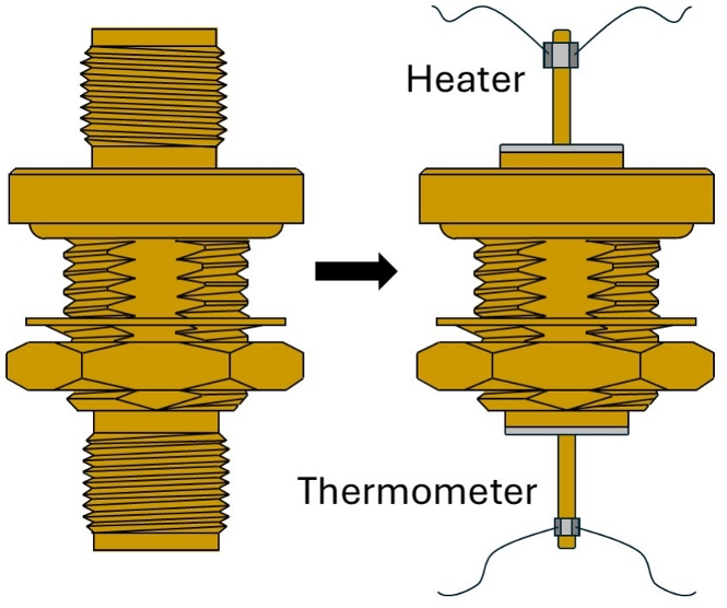
The measurement uses a thermal transresistance, defined near a chosen mixing-chamber temperature as the ratio between the downstream temperature rise and the applied heating power:
Its units are kelvin per watt. A smaller value indicates that a given heat load produces less warming at the measured downstream pin. Importantly, thermal transresistance is not microwave insertion loss and is not automatically identical to a component's ordinary two-terminal thermal resistance. The heater and thermometer occupy opposite pins, so the result probes heat transfer through the actual geometry of the device, including its path into the cold body. In a distributed thermal network those distinctions matter. [3]
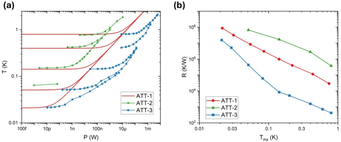
The three commercial designs performed very differently. One used a hermetically sealed inner-pin connection, another relied on a PTFE-spaced geometry, and a third employed a resistive microstrip structure on a quartz substrate. Of the samples tested, the quartz-based component had the lowest thermal transresistance and provided the most effective center-pin thermal anchoring. The PTFE-based part was weakest and exhibited comparatively long equilibration times. These results do not establish that all devices using a given dielectric will behave alike, or that 0 dB thermal anchors should replace the lossy attenuators needed for noise reduction. They show that a component's internal construction can decisively affect the temperature experienced by a sample even when its microwave loss specification looks unremarkable. [3]
Why equilibration is not instantaneous
Another lesson of the 2026 study concerns time. A refrigerator may reach a stable mixing-chamber temperature while an imperfectly anchored conductor is still approaching thermal equilibrium. A simplified lumped element has a characteristic thermal relaxation time approximately given by , where represents an appropriate thermal resistance and the heat capacity of the relaxing subsystem. Both quantities can depend strongly on temperature, so the simple form is a local approximation rather than a universal constant. The Purdue experiment found notably slow thermal response in its poorly anchored PTFE-based sample. [3]
That observation has immediate implications for how cryogenic experiments are diagnosed. A measurement performed immediately after changing a heat load, moving a cable, or warming a plate can probe a transient state. Likewise, a temperature logged at the mixing chamber may not record the slow drift of an electrical conductor with weak thermal contact. Good metrology requires thermometers at informative locations, repeatable thermal histories, and sufficient equilibration time. The distinction matters for interpreting apparent qubit temperature, device noise, or changes in coherence after hardware modifications.
The full problem is coupled. A coax has an outer conductor, an inner conductor, dielectric supports, and connectors, each with a different thermal-conductivity profile. A simple steady-state estimate for conductive heat through a homogeneous link of length and area is

A realistic cable requires summing the heat paths and accounting for thermalization at intermediate plates. The high thermal conductivity of copper improves thermal anchoring where a conductor is attached, but an uninterrupted high-conductivity copper line can also transport excessive heat from warm stages toward the mixing chamber. Materials such as stainless steel and superconducting niobium-titanium therefore appear in different portions of cryogenic microwave architectures, selected with both their thermal and electrical properties in mind. A desirable low thermal-conductivity cable and a desirable low microwave-loss cable are not always the same thing. [1][2]
From a cold plate to a cold electromagnetic environment
The 2026 results fit into a broader progression in cryogenic microwave engineering. Work by Yeh and collaborators characterized custom attenuators below 100 mK and found that microwave components dissipating power could have output noise temperatures well above the refrigerator's base temperature. Danilin and colleagues developed a frequency-dependent treatment of microwave-to-infrared photon propagation through real cryogenic coaxial lines. Other experimental programs have used qubits themselves as sensitive probes of the radiation entering their microwave environment. These methods approach the same engineering problem from different sides: thermal measurements determine where energy flows in the hardware, while noise and qubit measurements reveal the environment actually presented to the quantum device. [2][4][5][6]
One cannot infer microwave thermal occupancy from a single resistance measurement, nor infer the temperature of a coaxial center conductor from the nominal attenuation printed on a component. It is useful to separate at least three operational questions. How much conductive heat reaches a colder stage? What effective thermal occupation does a particular signal line present at the relevant frequency? And what dissipation occurs during the actual control and readout sequence? The first belongs primarily to heat-flow and contact engineering, the second to microwave noise and thermalization, and the third to a dynamic experiment-dependent power budget. Solving one does not automatically solve the others.
Readout channels illustrate the asymmetry. Input lines can use substantial cold attenuation because the intended drive can be made stronger at room temperature. An outgoing readout signal is tiny and cannot simply be thrown away before amplification. Its chain instead depends on isolation, filtering, carefully placed amplifiers, and noise-aware microwave routing. The cryogenic architecture is consequently a network of deliberately different thermal and electromagnetic boundary conditions rather than identical cables threaded through equally spaced plates. [1][4]
As quantum processors grow, these distinctions become architectural constraints. Hundreds or thousands of control and readout connections imply collective conductive loads, additional connectors, space occupied by thermal anchors, and more microwave power deposited on stages whose cooling capacity is sharply limited. Multiplexing, integrated cryogenic electronics, alternative cabling, and better thermal anchoring can reduce pressure on these budgets, but each introduces other requirements: crosstalk, impedance control, power dissipation, calibration, bandwidth, and maintainability. Even if a refrigerator can reach 10 mK without a processor, it does not follow that it can keep a densely wired, actively driven machine at the same physical and electromagnetic operating point. [1][2][7]
The temperature that matters is the one the qubit experiences
The deeper significance of the 0 dB experiment is methodological. Cryogenic engineering has long recognized the importance of thermal anchoring, but a center conductor can be mechanically hidden inside its cable, electrically essential to the experiment, and thermally invisible to the plate thermometer. Klomp and colleagues turned that hidden interface into a measured quantity, showing with three real components that nominally similar microwave hardware can behave very differently as a heat sink. Their work is a useful reminder that the label on a component may describe the property easiest to measure at room temperature, rather than the property that ultimately limits an experiment at millikelvin temperatures.
A convincing cryogenic quantum-hardware specification therefore needs more than a base-temperature number. It should describe the cooling power available at relevant loads, the thermal path from conductors to stages, the frequency-dependent noise occupancy incident on sensitive modes, and the heat generated by realistic operation. Where possible, these quantities should be measured rather than borrowed from idealized assumptions. The resulting picture connects refrigeration to quantum information: the thermal interface of a coaxial center pin can influence the noise environment of a resonator, the resonance can influence qubit coherence, and that coherence influences the resources required for error correction.
Near the bottom of a dilution refrigerator, the difficult engineering is often concentrated in seemingly ordinary components. A copper mounting plate, a tiny dielectric spacer, a microwave attenuator, and a threaded SMA connector help determine whether a quantum device truly experiences the cold environment its specifications promise. The last millikelvin is therefore not merely the last increment on a thermometer. It is the distance between a refrigerator that is cold and an entire experiment that has been successfully thermalized.
References and further reading
[1] Krinner, S. et al., Engineering cryogenic setups for 100-qubit scale superconducting circuit systems, EPJ Quantum Technology 6, 2 (2019). https://doi.org/10.1140/epjqt/s40507-019-0072-0
[2] Danilin, S. et al., Engineering the microwave to infrared noise photon flux for superconducting quantum systems, EPJ Quantum Technology 9, 1 (2022). https://doi.org/10.1140/epjqt/s40507-022-00121-6
[3] Klomp, J. T., Huang, H. & Csáthy, G. A., Effectiveness of Some 0 dB Cryogenic Microwave Attenuators as Thermal Heatsinks, Journal of Low Temperature Physics 222, 117 (2026). https://doi.org/10.1007/s10909-026-03453-0
[4] Gao, X. et al., Practical Guide for Building Superconducting Quantum Devices, PRX Quantum 2, 040202 (2021). https://doi.org/10.1103/PRXQuantum.2.040202
[5] Wang, Z. et al., Cavity Attenuators for Superconducting Qubits, Physical Review Applied 11, 014031 (2019). https://doi.org/10.1103/PhysRevApplied.11.014031
[6] Yeh, J.-H. et al., Microwave attenuators for use with quantum devices below 100 mK, Journal of Applied Physics 121, 224501 (2017). https://doi.org/10.1063/1.4984894
[7] A Survey of Microwave-Implemented Superconducting Qubit Control and Readout Circuits, IEEE Transactions on Quantum Engineering (2026). IEEE article and reference details.
Cover photograph: UCL Mathematical & Physical Sciences / Pavlos Apostolidis, London Centre for Nanotechnology, via Wikimedia Commons, CC BY 2.0. Original photograph cropped by the website's responsive cover-image layout. Other figures are credited alongside the images and reproduced under CC BY 4.0.